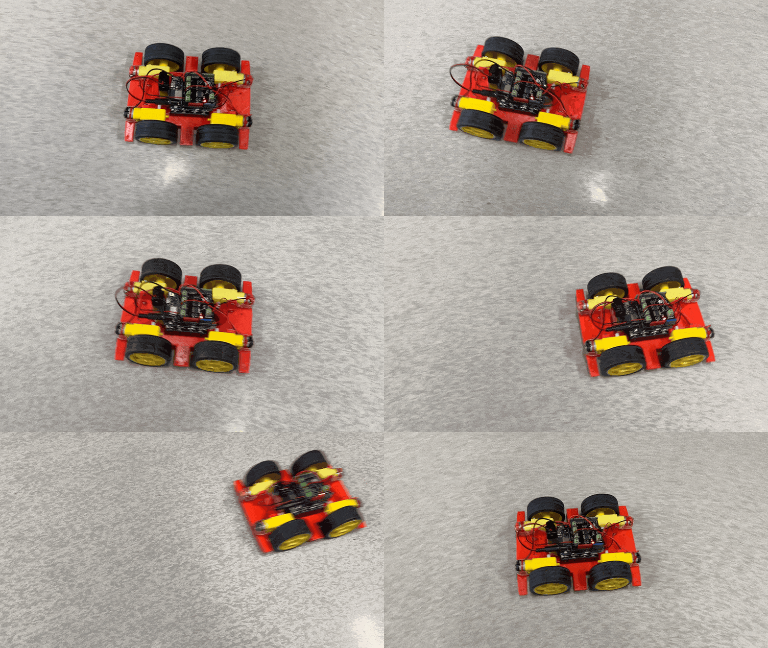
Build a 4WD car with an Arduino Uno and DFRobot DC Quad Motor Driver Shield
Arduino Uno tutorials
🕑 This lesson will take about 30 minutes
In this lesson, you will learn how to build a 4WD car using an Arduino Uno and the DFROBOT DC Quad Motor Driver Shield. This lesson will focus on getting the car moving, however, you can also add ultrasonic sensors to make the car autonomous or use a Bluetooth connection to control the car remotely.
The setup in this lesson uses an Arduino UNO R4 WiFi, however, the DFROBOT DC Quad Motor Driver shield is also compatible with other Arduino Uno boards. We’ll also use four DC motors, however, you can also build a car using just 2 DC motors at one end of the chassis and a trolley wheel at the other end of the chassis. You can also use the motor driver shield to build other non-car projects that require the use of DC motors.
What you’ll need
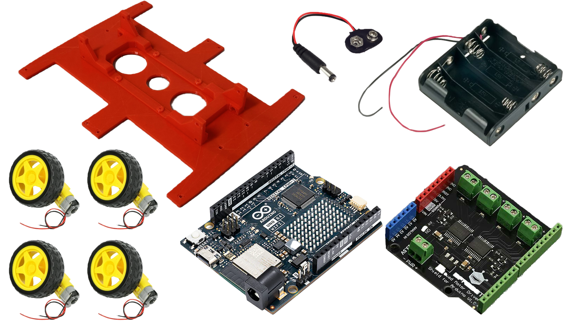
The components you will need for this project include:
1 x Arduino Uno board
1 x DFROBOT Quad DC Motor Driver Shield
1 x car chassis
4 x DC motors with wires
4 x wheels to attach to the motors
1 x 9V Battery connector (with barrel jack) to power the Arduino
1 x 4 AA Battery pack/compartment (with two wires) to power the motors
Batteries (1 x 9V battery and 4 x AA batteries)
USB cable
Step 1
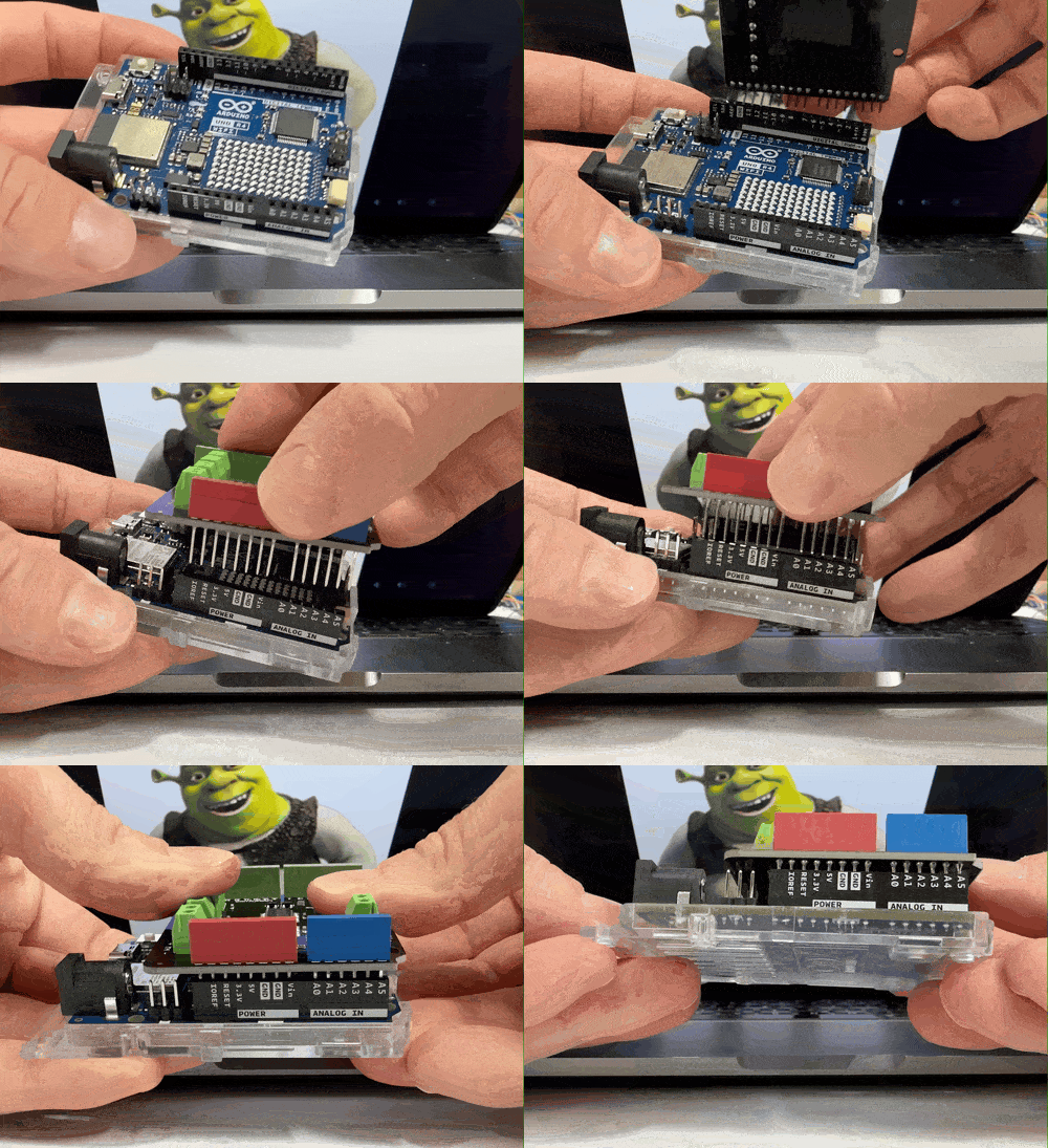
Attach the DFROBOT Quad DC Motor Diver Shield to the top of your Arduino board. Make sure that the pins on the bottom of the motor drive shield align correctly with the slots on the top of the Arduino to prevent damage to the pins.
Step 2
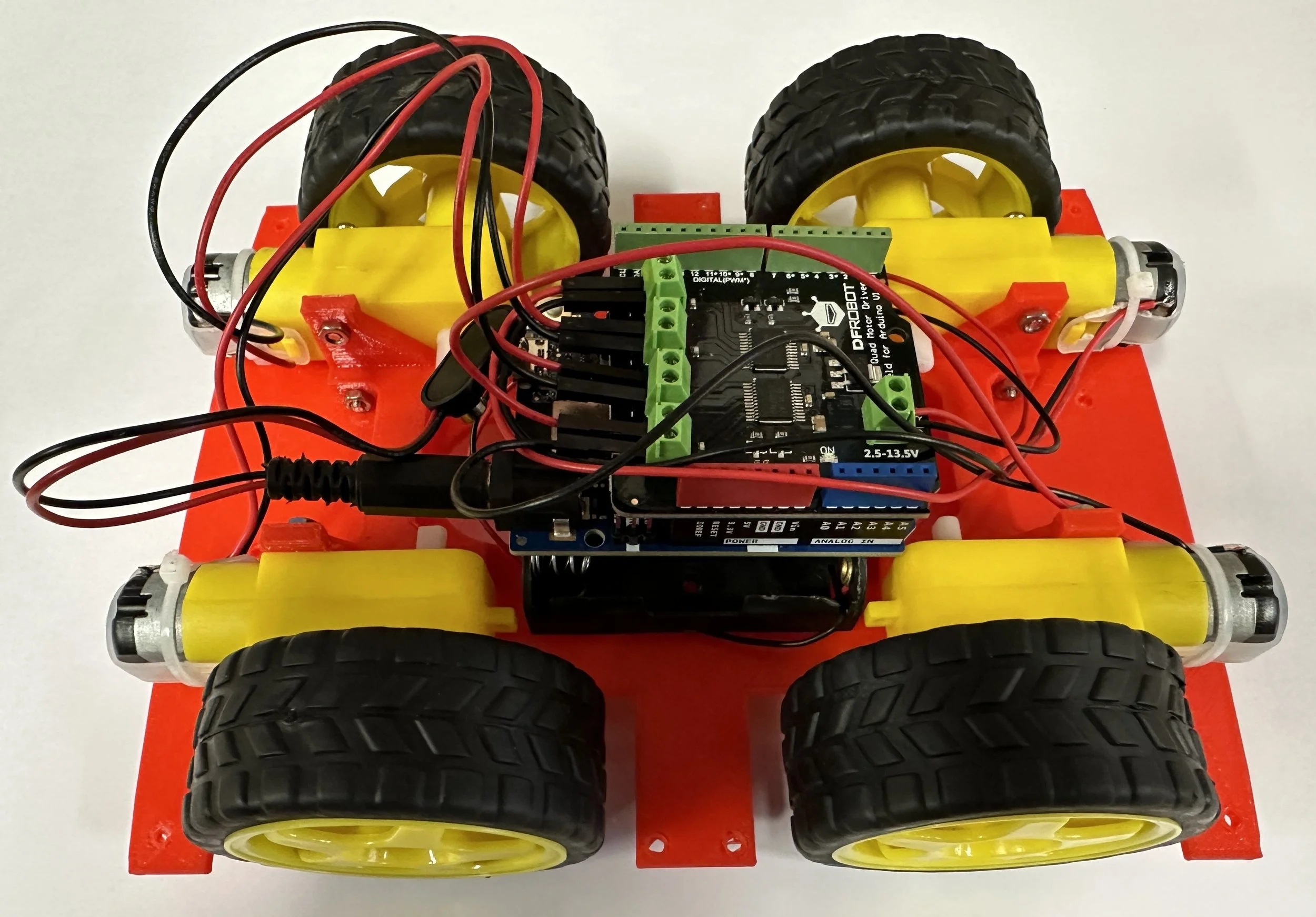
Attach the four DC motors and wheels to the vehicle’s chassis using small bolts and nuts. You can find a range of different 4WD car chassis to purchase online. In this example, we are using a basic 3D-printed 4WD car chassis.
Step 3
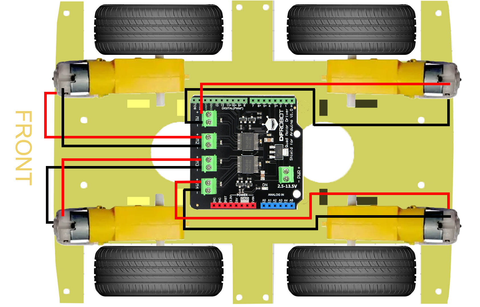
Attach the DC motors to the DFROBOT Quad DC Motor Diver Shield (placed on top of the Arduino board). Each motor should have a red wire and a black wire. On the motor driver shield, you will notice that there are labels M1, M2, M3 and M4 with a positive (+) and negative (-) sign next to each label. These are the slots for the four motors (motor 1, motor 2, motor 3 and motor 4).
To attach the wires, you will need to loosen the screws above each slot using a Phillips head screwdriver. Insert the wires into the relevant slots and then tighten the screws while holding the wires in place. The screws will clamp the wires in their slots so they don’t fall out.
The red wires for each motor are to be inserted into the positive (+) slots, and the black wires for each motor are to be inserted into the negative (-) slots.
For example (if looking at the car front-on):
the rear left motor’s red wire will attach to the positive (+) slot for M1 and the black wire will attach to the negative (-) slot for M1.
the front left motor’s red wire will attach to the positive (+) slot for M2 and the black wire will attach to the negative (-) slot for M2.
the front right motor’s red wire will attach to the positive (+) slot for M3 and the black wire will attach to the negative (-) slot for M3.
the rear right motor’s red wire will attach to the positive (+) slot for M4 and the black wire will attach to the negative (-) slot for M4.
Step 4
Attach the red wire from your AA battery pack to the positive (+) slot on the other side of the motor driver shield where it is labelled PWR (power). Then attach the black wire from the AA battery pack to the negative (-) slot where it is labelled PWR. This battery pack will be used to supply power to the four motors. Do not insert the AA batteries into the battery pack yet. Note: You might want to add a switch to your battery pack so that it can be turned on and off without having to remove the batteries.
Step 5
Now attach the 9V battery connector (with the round barrel-jack plug) to the round barrel-jack connector on the Arduino Uno board. This will be used to provide power to the Arduino Uno board when it is not connected to the computer. Don’t attach the 9V battery yet.
Step 6
The final step is to upload the code to the Arduino board and then insert the AA batteries and 9V battery to supply power to the Arduino and motors. The following example code will move the car back and forward repeatedly (2 seconds forwards, 2 seconds backward, repeat…). You can experiment with modifying the code to make it move in different directions and at different speeds. You may also need to alter the code depending on which way your motors and the red and black wires are facing. Once you are familiar with the code, you can add an ultrasonic sensor or use Bluetooth to make the car autonomous or remote-controlled.
Here is the example code to get started:
Video of the car moving:
What’s next?
The DFROBOT motor driver shield uses the following digital pins on the Arduino board:
Digital pins 3, 4, 5, 6, 7, 8, 11, 12
This means the following pins are still available to use to connect other components such as ultrasonic sensors:
Digital pins 0, 1, 2, 9, 10, 13 and all analogue input pins
The motor driver shield also provides additional slots for 3.3 and 5V power output, GND, and VIN (voltage input).
Using these other available Arduino pins, you could:
Attach ultrasonic sensors to make the vehicle detect obstacles and move around autonomously.
Attach LED lights for headlights and brake lights
Attach servo motors if you’re building a robot (eg. to create a claw to pick up objects)
Attach an IR (infrared) or Bluetooth module to control the car remotely using a smartphone app or remote controller
Or use the built-in Bluetooth module if using the Arduino UNO R4 WiFi board.
For more information about the DFROBOT Quad Motor Driver Shield, visit the product wiki.

