Using a light sensor and Arduino to control an LED light
Arduino Uno tutorials
🕑 This lesson will take about 20 minutes
In this lesson, you will learn how to use an Arduino Uno and photosensor or LDR (light-dependent resistor) light sensor to control an LED light. A photoresistor, also known as a light-dependent resistor (LDR), is a light-sensitive device that can indicate the presence or absence of light, or measure the light intensity (brightness). You can learn more about LDRs here.
The LDR will take regular readings and turn an LED on in low-light conditions, and turn the LED off in bright-light conditions.
The lesson will cover two different types of light sensors:
Generic LDR light sensor (it has 2 pins)
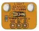
Freetronics LDR light sensor (it has 3 pins – GND, OUT, and VCC)
Generic LDR (with 2 pins)
Required parts
The project requires:
1 x Arduino Uno board
1 x LED light
1 x LDR (light sensor)
1 x breadboard
6 x male-to-male jumper wires
1 x resistor (10k Ohm resistor) if using the light sensor with two pins
1 x resistor for the LED (can be any value between 100 Ohms and ~10K Ohms). We will use a 220 Ohm resistor in this example.
How does it work?
We will use the light sensor to get light readings at a set interval (eg. once per second). The light sensor will return values representing different levels of light eg. between 0 and 1023 (where 0 means very dark and 1023 means very bright). You can specify a value that, when the sensor reading is less than this amount, an LED light will be turned on, and when the light is greater than this amount, then the LED light will be turned off.
To work out the specific value from the sensor that should trigger turning the LED on, you will need to take some test readings from the sensor. You can do this by using the Serial Monitor to display readings when testing the light sensor under different light conditions to calibrate the project.
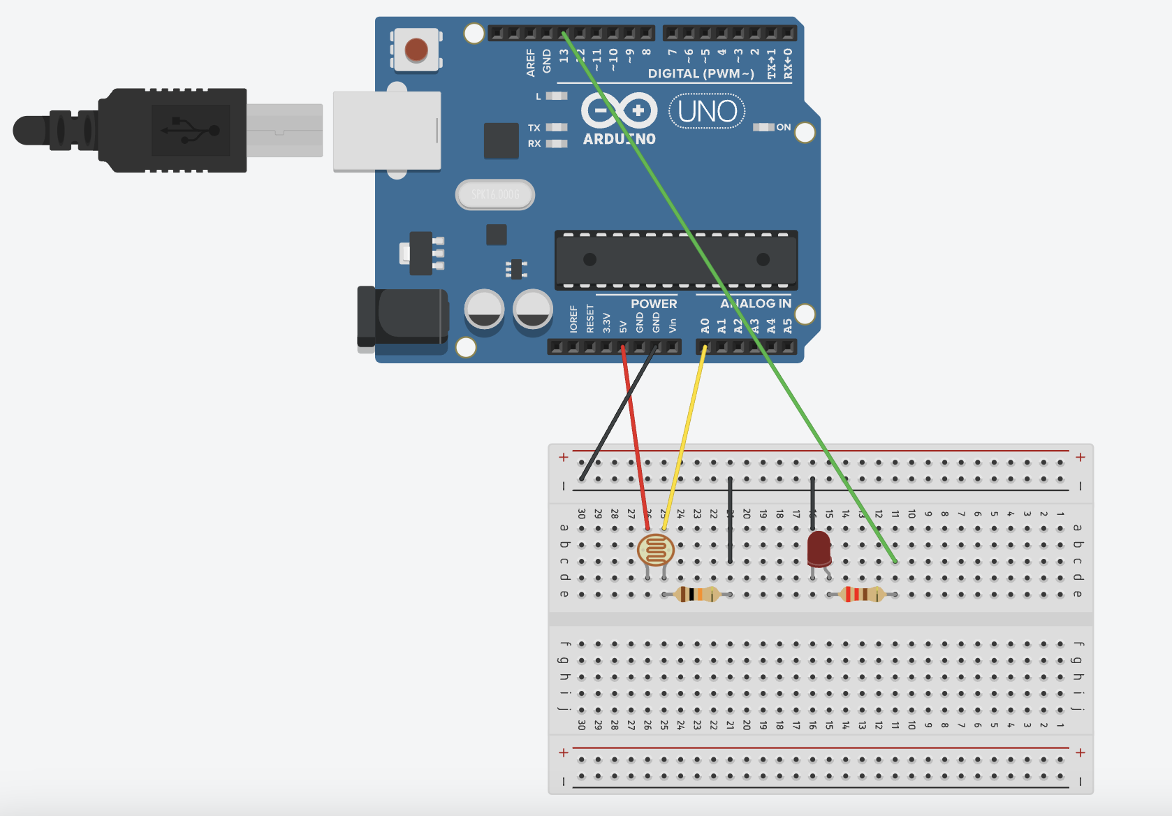
Wiring schematic for the generic LDR light sensor (with 2 pins)
Below is the schematic showing the 2-pin LDR light sensor and an LED connected to the Arduino via a breadboard.
Connect one pin of the light sensor to 5V on the Arduino and connect the other pin on the LDR to analog input pin A0 on the Arduino board via the breadboard.
GND from the Arduino is also connected via a 10k Ohm resistor on the breadboard to the LDR.
Connect digital pin 13 on the Arduino to the long pin of the LED via a 220 Ohm resistor.
Connect the short pin of the LED to GND on the Arduino via the breadboard.
Note: When testing, if the LDR is not working, you may need to flip it around as the two pins may be connected in the incorrect order.
Code for the generic LDR (with 2 pins)
Here is the source code for the LDR (light sensor) that has two pins shown in the schematic above.
Upload the code to the Arduino. In the Arduino IDE, click Tools > Serial Monitor and set the baud rate (in the dropdown box) to 9600 baud to view the light sensor readings received from the Arduino when it is connected via USB to the computer (as shown in the image below). You can use these readings to test the light sensor and determine an appropriate value for low-light conditions to specify when the LED should turn on.
Test the light sensor by covering it with your hand or shining a light on it to see the different light sensor readings.
Note: If the LDR is not getting accurate readings, try swapping the light sensor pins around as they may be connected in the wrong order.

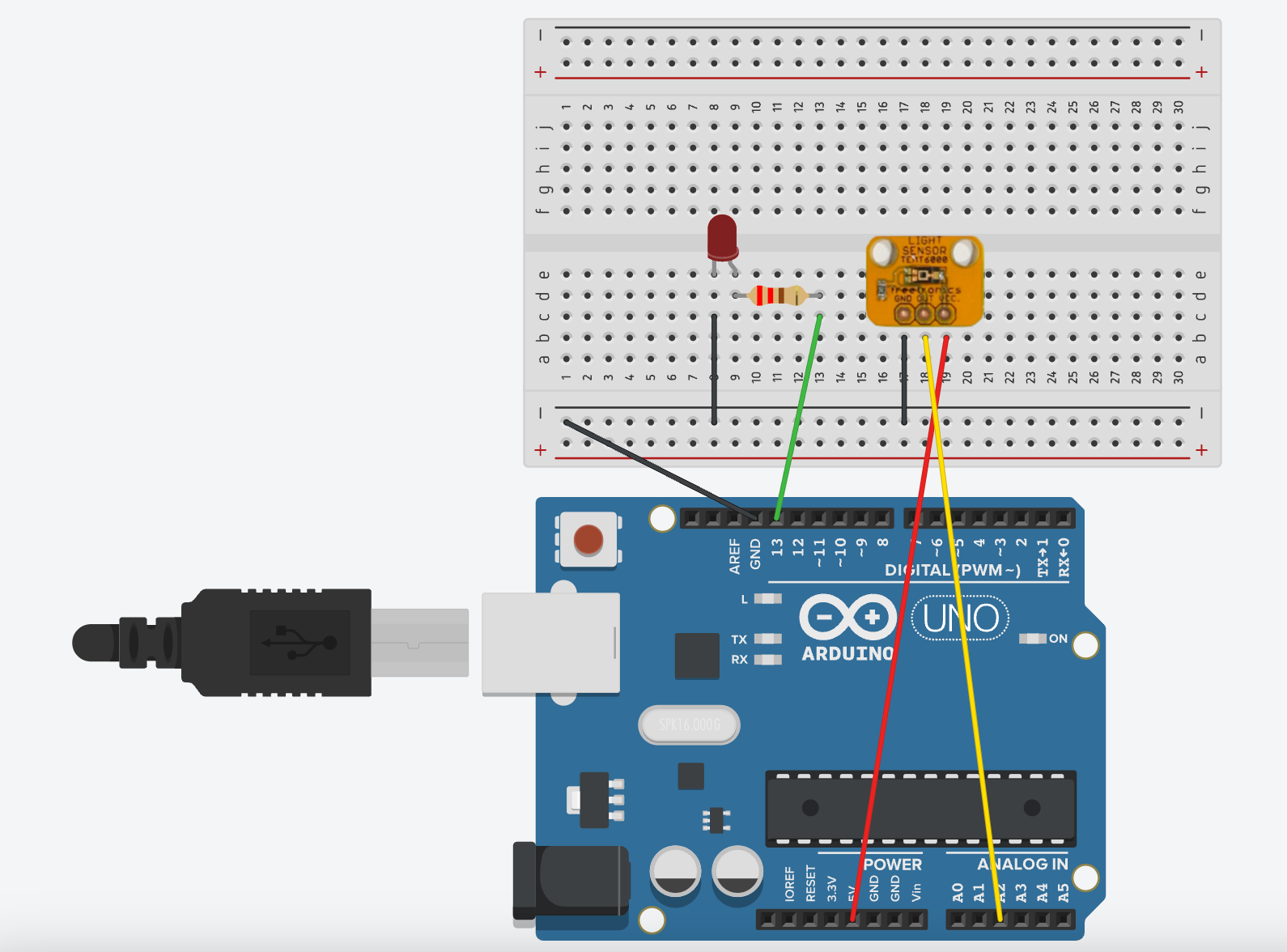
Wiring schematic for the Freetronics Light Sensor (with 3 pins)
Below is the wiring schematic showing how to connect the Freetronics LDR to an Arduino.
Connect the long pin of the LED to Pin 13 on the Arduino and the short pin to GND on the Arduino via the breadboard.
Connect GND on the LDR to GND on the Arduino board, OUT on the LDR to analog pin A2 on the Arduino, and VCC on the LRD to 5V on the Arduino.
Code for the Freetronics LDR (with 3 pins)
Here is the source code for the Freetronics LDR. Create a new sketch in the Arduino IDE software and upload this code to the Arduino.
Upload the code to the Arduino. In the Arduino IDE, click Tools > Serial Monitor and set the baud rate (in the dropdown box) to 9600 baud to view the light sensor readings received from the Arduino when it is connected via USB to the computer. You can use these readings to test the light sensor and determine an appropriate value for low-light conditions to specify when the LED should turn on. If you are only logging numbers (and no text) to the serial monitor, then you can also use the Serial Plotter to plot the values on a graph. Test the light sensor by covering it with your hand or shining a light on it to see the different light sensor readings.